More progress in porting Loser Corps to the ESP32 (see all posts about the port).
Even though there's nothing really exciting to report, this is a very long post because there's a lot of small changes:
- Wiimote support
- New VGA DACs
- Rewriting the VGA output code
- New font
Wiimote Support
The game now supports the Wiimote controller (via Bluetooth) using
takeru's Wiimote library. I had
to make a very small change to use it: I added a void * parameter to
the callback function, so it can update the state of the controller
object without forcing it to refer to the global binding.
The library works perfectly, the only slightly annoying thing is that I haven't figured out how to permanently pair the controller with the ESP32, so every time the ESP32 restarts you have to press the Wiimote buttons 1 and 2 at the same time to make the Bluetooth connection. Not a big deal, but it could be better.
New VGA DACs
I made a new VGA connector with new digital-to-analog converters (DACs). The old ones are slightly wonky because I didn't have resistors with good values when I made it, so I finally got some new resistors and made a new one:
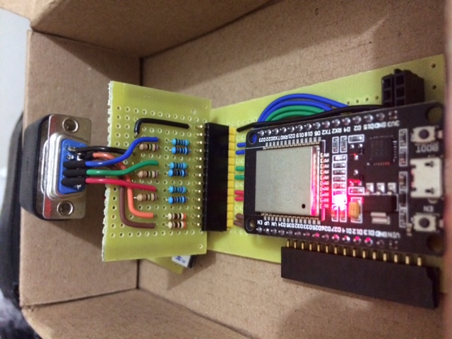
For comparison, here's the old one:
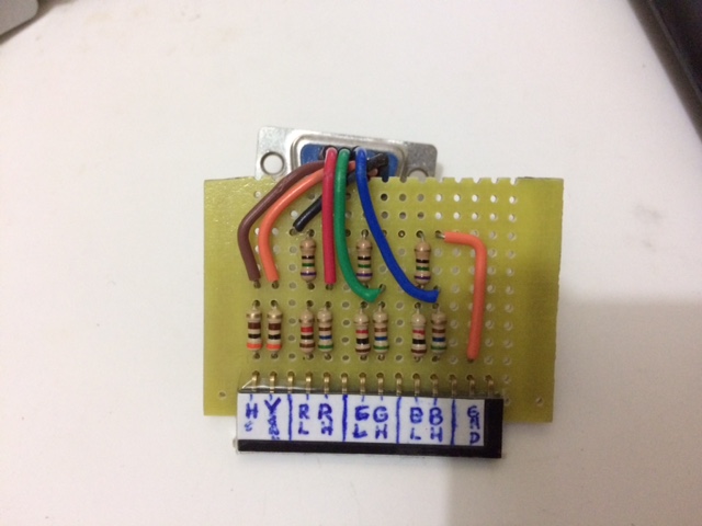
To see why the new DACs are better than the old ones, we have to talk about how the VGA color signal is generated. The monitor wants to receive each color component (Red, Green, Blue) in their own wire, with a voltage between 0V and 0.7V indicating its intensity. To produce an image, the voltage has to be changed as the monitor sweeps the screen to draw the pixels: each pixel is drawn with the RGB intensity corresponding to the voltage of the red, green and blue wires at the time it's being drawn.
The ESP32 only has 2 internal DAC outputs, so we can't use them to create the 3 voltages we need for the RGB wires (even if it had 3, its DACs aren't fast enough to generate the signal we need at over 12MHz). So we make the ESP32 output each color component as multiple digital pins: in our case, we use 2 pins per component. Since a digital pin has two logical values (0 and 1), each component has 4 possible combinations (00, 01, 10, 11), and the DAC has to convert these to 4 voltages between 0V and 0.7V. Ideally, we'd like to map them like this:
| pin values (from ESP32) | intensity | output voltage (to VGA monitor) |
|---|---|---|
| 00 | 0% | 0V |
| 01 | 33% | 0.23V |
| 10 | 67% | 0.47V |
| 11 | 100% | 0.7V |
The ESP32 output pins give 3.3V when high (logical 1) and 0V when low (logical 0), so we can build a small circuit connecting them to resistors to generate the desired output voltages:
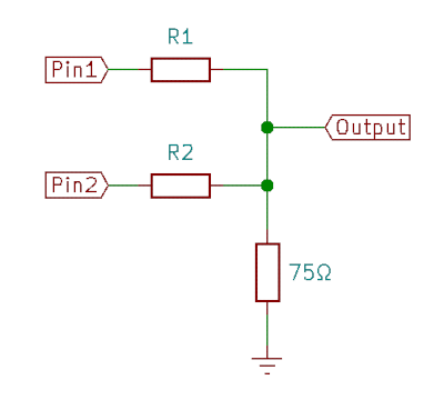
That's the DAC. We just have to choose values for R1 and R2 so that when Pin1 and Pin2 are high/low we have the desired voltage in output as shown in the table above. (By the way, the 75Ω resistor is there for impedance matching with the monitor -- I don't think it's really right, but I don't know how to match the impedance properly).
The old DAC had resistor values of 1KΩ and 560Ω, which is what I had available at the time. The new DAC has 1KΩ and 470Ω, which outputs voltages closer to what we want:
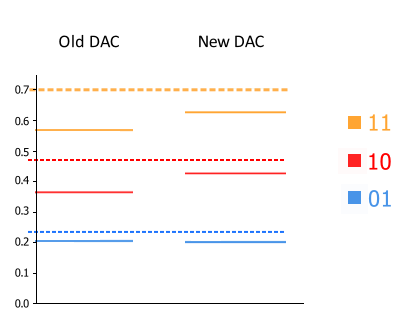
The dotted lines show the theoretical best values for each pin value
except for 00, which has the trivial-to-generate voltage level of
0V. The new DAC is overall closer to the theoretical best, but most
importantly, it has more consistent spacing between the levels, while
the old DAC has the interval between 01 and 10 smaller then the other
ones.
I'm not sure the image result is that different, but for the record here's a photo of the game running with the new DACs:

Rewriting the VGA Output Code
I ended up rewriting the VGA output code. I was using bitluni's excellent ESP32Lib, but that library does a lot of stuff we don't need. That makes the code larger and also more complicated: when reading the code, I had trouble following exactly how things are done with the code written in C++ with multiple inheritance.
So to make sure I understood every detail, I ended up rewriting the code in plain C style. My code supports only double-buffered output, and changing the resolution requires altering the appropriate constants by hand (I might make it easier to change it if I end up using this code for something else). It also doesn't have any drawing API, all drawing must be done by writing directly to the framebuffer -- which suits the game just fine, because I was already doing that with ESP32Lib.
My only improvement over ESP32Lib was making the I2S system trigger an interrupt at the end of each frame (the interrupy simply increments a frame counter). With that, the main game loop can now wait for the end of the frame to swap the framebuffers and start drawing again (basically a vsync). That removes the annoying horizontal line from the screen which happens when the image is updated while it's being drawn, and also forces a constant framerate (that's why that photo above shows 60fps).
It's still possible to disable the vsync (returning to the old variable framerate and annoying horizontal line), which I do occasionally to check the performance of the game.
New Font
Since I'm not using ESP32Lib anymore, I had to make my own font and font-rendering code (which is pretty unoptimized, but for now it doesn't matter since I'm only using text for debugging). I used Krita to draw the font because it's easier to draw pixel-by-pixel with it than with Gimp.
Here's an image of the 6x8 font:
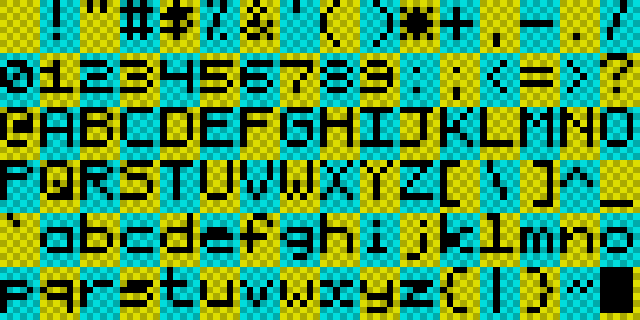
(The yellow/greenish background is what I used when drawing the font.)
Next Steps
I'm not sure what I'll do next: probably either sound or network. For network, I haven't even decided if I'll use ESP32's "ESP-NOW" protocol or normal WiFi/IP, but it will be fun to investigate the pros and cons of each one.