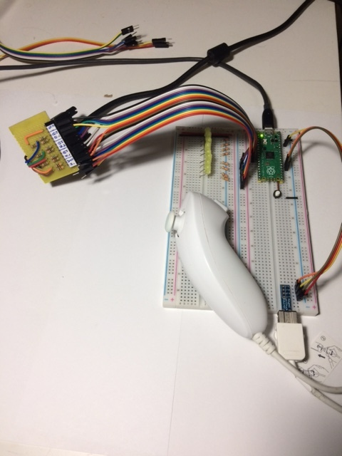
In the process of creating a new perfboard to connect the Pico to a VGA monitor, I realized that all the VGA DACs I made so far are using only half the voltage range, which results in a very dark image all around.
Here's what I figure happened: the initial schematic I drew for a the DAC used a 75 Ohm resistor to ground, which I initially put there to represent the one inside the monitor (so I could calculate the values for the other resistors). Later, when building the boards, I put that 75 Ohm resistor on the board, so there were TWO 75 Ohm resistors to ground in parallel, which results in everything being roughly half the voltage it's supposed to be. Later, when looking at that schematic, I though I had put that resistor there for impedance matching (which I knew was not really right), so I left it alone.
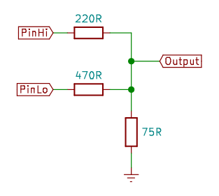
When I started builiding a perfboard for the Pico (to make it more permanent that the breadboard I had last week), I decided to calculate everything from scratch, and I realized the mistake. My correction still uses a 75 Ohm to ground, but the other resistors have much lower values to compensate. The current drawn from the pins is much larger, but still below 15 mA, so I think that will bo OK for the Pico and the ESP32.
Here's the new schematic for each DAC:
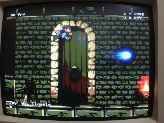
And here's the Loser Corps screen with the new DACs:
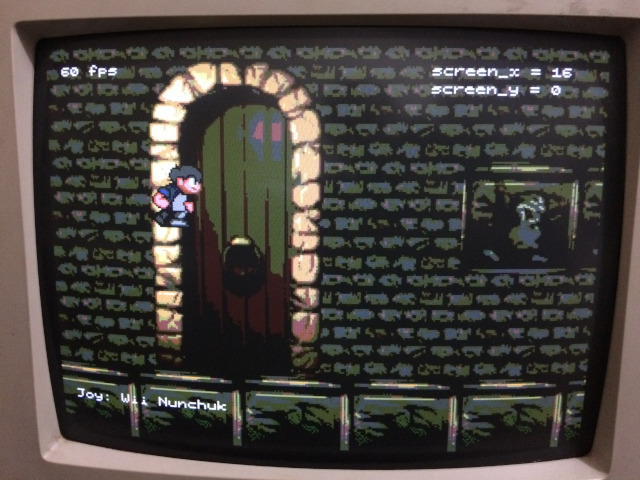
Here's the screen with the old DACs for comparison:
The new perfboards have the resistors soldered on the main board where the the Pico and the ESP32 are inserted, and the small boards with the VGA connectors have with nothing but female headers with 6 pins to connect to the main board. This way, if I ever want to change DACs again, I don't have to solder wires to the VGA connector (which is a very unpleasant job).
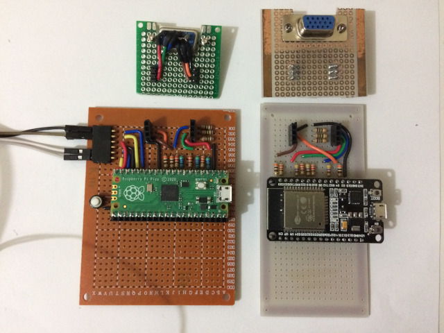
The Pico board has two sets of connections for I2C (for the Wii Nunchuk). I'll add these connections to the ESP32 board later.

